How to retrofit a solar panel and solar regulator to a Simpro Multi-Tip bin lifter.
Procedure
- Remove the main powerpack cover and disconnect the battery cables.
- Sit the frame mount angle in place at the top of the mast stiffener channel as shown – 150mm down from the top - and mark and drill 2x 8.5mm holes and fasten securely with M8x70 bolts and nuts.
- Place the solar panel face down on a clean soft surface, feed output wires through the hole in the centre of the mount bracket and then bolt it down with 4x M8 bolts and nuts.
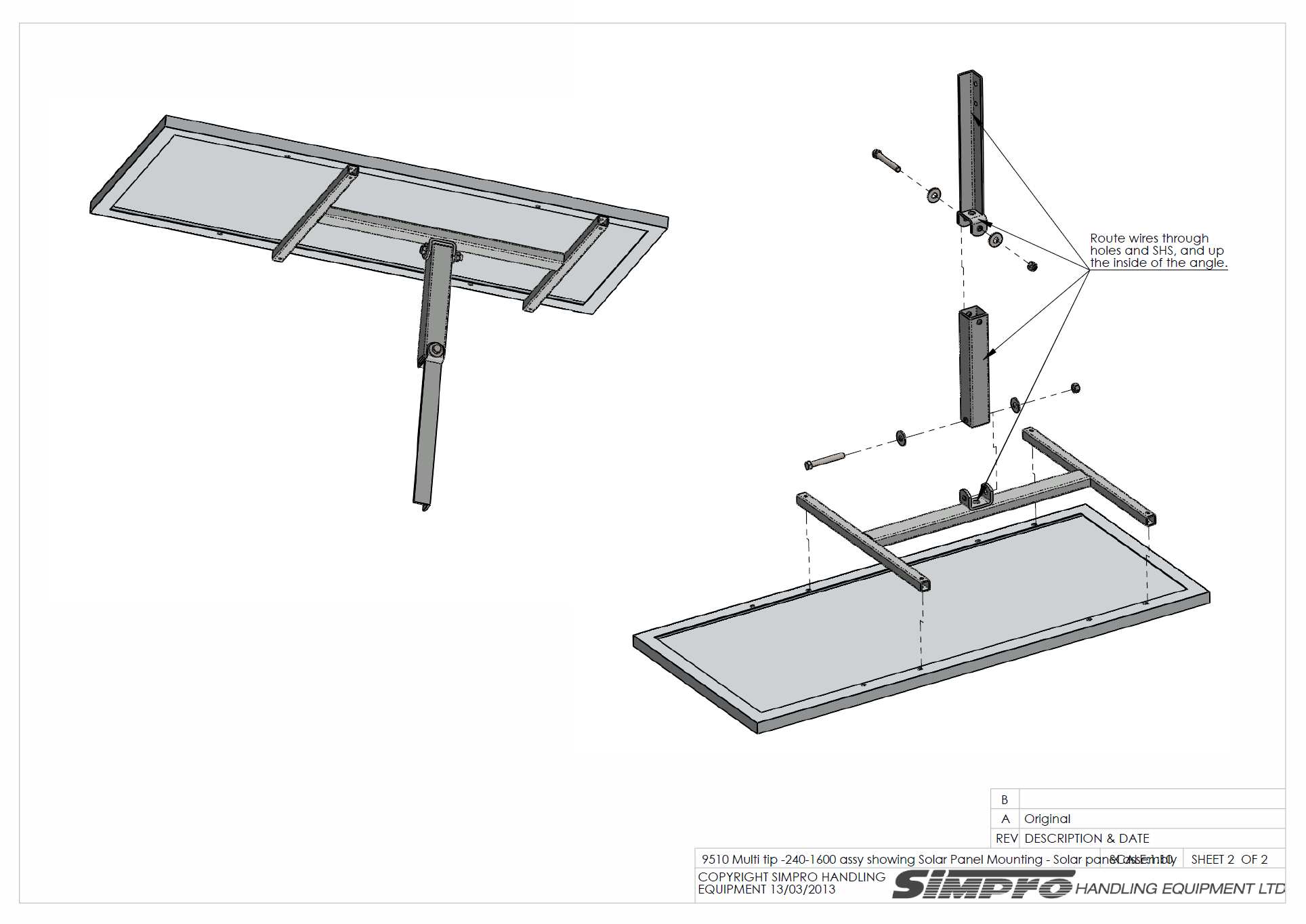
- Feed output wires through the 50x50 SHS and bolt this to the mount bracket with M12x80 bolt and locknut and tighten firmly.
- Connect long 2-core wire to the wires from solar panel with ‘bullet’ crimps, ensuring that the core wire with red strip is connected to the positive output.
- Carefully lift the panel and brackets up to the top of the Multi-Tip mast.
- Feed 2-core wire in through the hole in the angle bracket, down the corner of the angle and into the hole in the top mast cap, clipping in place with plastic clip. Locate SHS into main angle bracket and fasten with M12x80 bolt and locknut, tighten firmly.
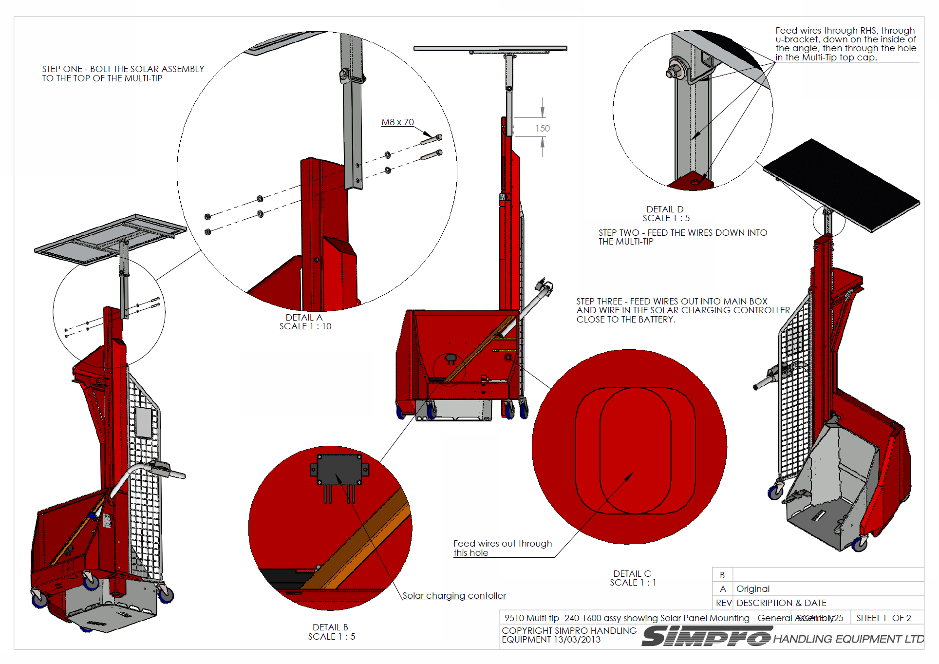
- Continue to feed the 2-core wire down inside the stiffener channel, out the square hole and into the main powerpack box.
- Mount the controller on the inner face of main box above the battery, by drilling 2 x 5mm holes and screwing in place with M5 screws and nuts.
- Connect main supply wires to the ‘input’ wires of the controller with bullet connectors, ensuring correct polarity. Input side is shown with a picture and words ‘solar cell’. Neatly route the cable with cable clips.
- Connect short battery wires to ‘output’ wires from controller using bullet connectors. Output side is shown with a picture and words ‘battery 12vdc’.
- Reconnect the main red and black battery cables to the battery along with ‘output’ wires, again ensuring the wire with red stripe is to the positive terminal. Tighten firmly.
- Solar panel is now connected and ready to use. Place in a sunny location and adjust the angle of the panel to get maximum direct light. Check the top of the controller for two little LED’s, if the green on the left is on, it indicates the battery is ‘full’. If the orange on the right is on, it indicates it is ‘charging’. Replace the main box cover and tighten screws firmly.


The panel output varies with available light, but will put out over 6amps in full light, allowing the 18ah battery to be charged in approximately 3 hours. The controller will automatically turn off once full charge is reached. The mains charger is still connected and can be used at the same time or as back-up in case of insufficient sunlight.