How to retrofit push-button controls to a compressed-air powered Quikstak “smart-stacker” from Simpro.
Parts required:
- ⅜” poppet valve
- 1/8” pilot roller valve and mount bracket
- Air cylinder for lowering valve and mounting bracket
- 4mm tubing
- Assorted 4mm fittings
Tools required:
- Standard spanner set
- Power drill, 22mm holesaw, 3mm, 6mm drill bits
- Nylon hammer
- Tube cutter or knife
Procedure:
- Disconnect the air supply, remove the access panel from the fibreglass cover.
- Unscrew the control lever from the bracket and remove the fitting from the end of the main inlet pipe.
- Remove the plastic retainer clips holding the fibreglass cover on. If they do not come out easily, they may be drilled out. Remove the cover.
- Determine the best position for the Emergency Stop and Raise/Lower buttons, and drill 22mm holes (ideally with a holesaw). The button heads have a very small locating tab to stop them turning. Determine where this will be when the button is mounted and drill a 3mm hole just on the edge of the 22mm hole.
- Mount the Emergency Stop and Raise/Lower buttons. Clip the double valve assembly under the Raise/Lower head, and the single valve under the E-stop.
- Disconnect the linkage to the valve spool, and unbolt the fork plate on the lowering valve.
- Slide the spool out of the aluminium valve body, then unscrew the valve from the power-pack (leave the short piece of ⅜” pipe in place). It may be necessary to remove the exhaust hose to get the valve off.
- Remove the ⅜” to 12mm elbow fitting from the valve and screw it into port 1 of the new ⅜” poppet valve.
- Unscrew the cast aluminium bracket holding the lever assembly for the lowering valve cartridge.
- Fit the new air cylinder assembly.
- Wind the new ⅜” poppet valve onto the motor inlet pipe (port 2); ideally it should finish with the pilot port towards the top. Reconnect the exhaust hose if disconnected.
- Mount the roller valve
- There should be a 1/8” BSP port on the filter/regulator which is normally used for a gauge. Wind a 1/8” to 4mm elbow fitting in for the supply to the control valves.
- Connect the 12mm tubing from the air prep unit to the poppet valve, and connect 4mm tubing between the various control valves as shown below. Leave the fibreglass cover on the ground at this stage, and make sure the tubing is long enough to lift it over the rear tiller bracket and put into place.
- Temporarily reconnect the fitting onto the main air inlet pipe and reconnect to the air supply.
- Test the operation of the valves:
- Pressing the emergency stop should prevent both Raise and Lower buttons from working.
- When the Raise button is pressed the motor should run, but when the forks reach the top (de-activating the roller valve) the motor should stop.
- When the Lower button is pressed the forks should descend.
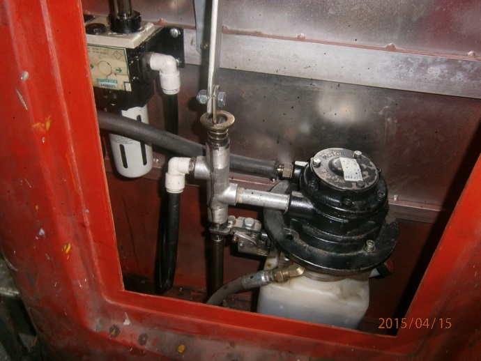
- While the cover is off, we recommend to clean the filter bowl, and check and adjust the oil flow of the lubricator.
- When satisfied with the operation of the machine, refit the fibreglass cover using the plastic clips supplied.
