How to retrofit an IDEC door interlock system to an older-model Simpro Dumpmaster bin lifter.
Parts required
- Idec lock, HS5E-D4403-G (0790050206), with 3- & 4-way plugs on lead.
- Lock actuator, HS9Z-A51A (0250050065) or HS9Z-A51 ()
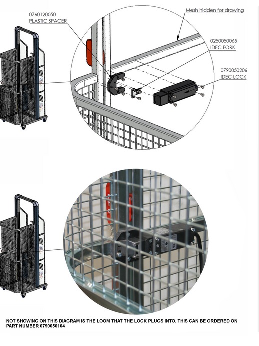
- Plastic actuator mounting bracket (0760120050)
- Idec door lock extension loom (0790050104)
- 12 to 24vdc converter, with extended wires and plug pre-fitted (0790050201)
- Microswitch mounted on bracket (0250050137 & 0250020043)
- 25mmOD/19mm ID rubber grommet (0250040546)
- 11.5mm plastic body plugs (4 off)
- 75 x 50 rubber end cap (1 off)
- M4 x 16 screws (4 off)
- M4 x 12 screws (6 off)
- M4 Nylock nuts (10 off)
- M4 flat washers (10 off)
- 100mm cable ties (12 off)
- Black rubber Grommet 11.1/6.4/1.6 x 1 (on microswitch bracket)
Tools required
- Electric drill and drill bits
- M4 tap
- 25mm holesaw
- Screwdrivers, spanners
- Drilling templates from Simpro
Procedure
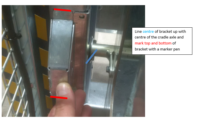
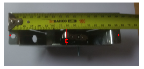
- With the cradle sitting on flat, level ground, hold the ‘microswitch bracket’ against the inner corner of the mast, and line the centre of the bracket up with the centre of the cradle axle.
- Drill the 3 holes with a 3mm drill bit, then raise the cradle and mark a centre hole for the microswitch to pass through. Drill the centre hole out to 16mm. The microswitch roller will be triggered by the cradle axle roller as it comes down.
- The microswitch cover bracket may be attached using self-tapping Tek screws, or with M4 x 16 machine screws. If the latter, thread the other 3 holes to M4 but don’t mount the microswitch yet.
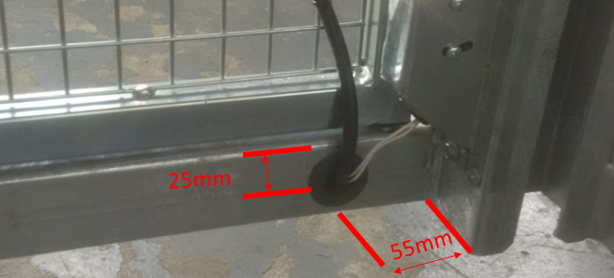
- Drill a 25mm hole in the base frame using a hole-saw, with the centre 55mm away from the mast and 25mm below the top face. Insert the rubber grommet.
- Hold the microswitch bracket in place, and attach with 2 x M4 screws or Tek screws.
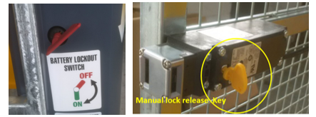
- If the machine has a Battery Isolator, remove the Isolator key, then remove the ram cover and outer power-pack cover.
- Open the door, prise out the old plastic end-cap switch, and disconnect the orange wire from the stainless-steel contact inside the end-cap, and from the connector by the power-pack. This is no longer needed.
- Cut the protruding part of the 8mm pin off at the bottom of the door frame.
- Using a jig available from Simpro, drill 3mm pilot holes in the side guard and the door frame. Mark and drill as below:
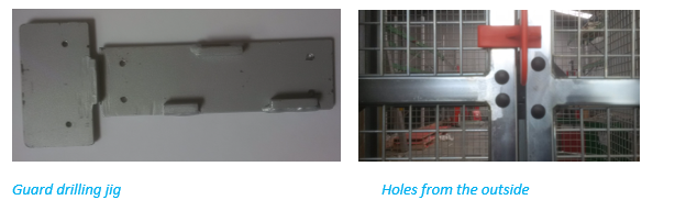
- Drill the 2 holes in the upright member of the side guard, and the door through both sides of the square section to 4.5mm, then redrill the holes on the outside face of these 4 holes to 11.5mm.
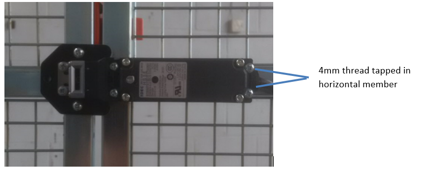
- Thread the two holes in the horizontal member to M4.
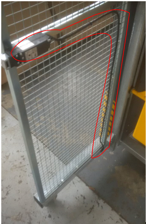
- Mount the door lock, using M4 x 40 screws – 2 threaded into the square section and 2 with Nylock nuts held with a small socket. Mount the actuator and plastic packer using 2 x M4 x 25 screws and Nylock nuts. Put plastic blanking plugs in the outer holes.
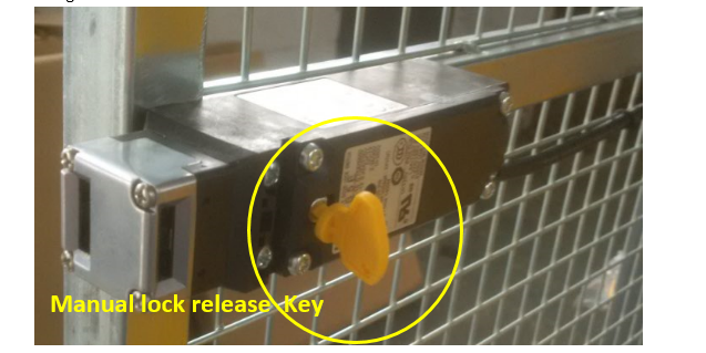
- Turn the manual release cam on the lock using the plastic key supplied, then open and shut the door to make sure the actuator locates correctly into the lock. Leave the lock released for the time being.
- Cable-tie the cable for the door lock along just below the centre member, and down beside the vertical member. Connect the 4-way plug on the flex to the extension loom, and pass the flex and extension loom through the grommet and up through the hole in the top of the base frame.
- Mount the 12 to 24vdc converter about half-way up the inner panel. Connect wires as follows:
- Connect the long red wire into the side of the key switch going to the Raise/Lower switches.
- Connect the black wire to the ‘lower’ 4-way plug going up to the controls, into the 2 black wires that are joined on the 12-24v converter.
- Connect the orange wire onto the bullet connector on the black wire lowering solenoid and motor relay.
- Mount the 12-24v converter to a convenient place in the Powerpack control cover with 4mmx12 pan head screws and nylock nuts.
- Plug the ‘Idec extension loom’ into the new 4-way socket.
- (If applicable) Insert the isolator key and turn the isolator on. Turn the lock cam back to the locked position and shut the door.
- Check the operation of the lock as follows:
- The cradle should only be able to go up or down when the door is shut
- The door should only be able to be opened when the cradle is on the ground.
- The door should be locked when either the isolator or key switch are off.
- The position of the microswitch can be adjusted if necessary to ensure it works reliably.
- When satisfied that everything is working correctly, refit the outer power-pack cover and ram cover.


